(Horizontal "FLAT" Design)
Created by: Jeryd Lassley
Date: November 16th - 20th, 1998
This engine was designed and created by Jeryd Lassley.
I must admit that during the laboriously filled timeframe that it took
Jeryd to build this engine, I was 98% skeptical that it wouldn't work.
Since Kevin and I had taken quite a few of the technic pieces to be used
in the first 2 LEGO engines, this left the odds stacked against Jeryd.
Yet somehow, he managed to get this baby to run and really quite well.
The crankshaft, unlike the previous 2 designs, is counter-balanced for
smooth operation. It uses the same flywheel setup as Engine #2 and
similar arrangement for the valve setup. We were out of pulleys (which
are so helpful in "dialing in" the valve timing) and this left Jeryd at
a distinct disadvantage. He managed to use gears with 2 collar/rivet
assemblies per gear instead of the 3 collar/rivet assemblies per pulley
on the previous 2 designs. I believe this engine would run better
with the pulleys but Jeryd had no choice and to my amazement, he got this
engine to run well and run very smooth!
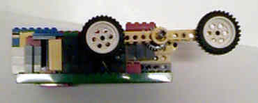
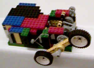
From the side, you can see that this engine is a very low-profile design
and it fits on a flat 2x lego plate. You can't see it in this picture
but you can tell that the angle of the connecting rod to the crankshaft
is set so that halfway thru the power stroke (which is 90 degrees CCW from
TDC) the connecting rod is 90 degrees to the crankshaft so that maximum
power is applied to the crankshaft.
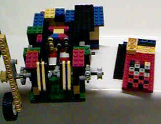
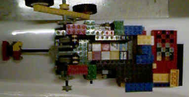
Another MAJOR hurdle to building this type of design is trying to get the piston to seal in the cylinder wall. When going with the standard vertical piston travel setup, you have the flat faces of the blocks on all 4 sides which seal against each other. When laying the piston on its side however, you no longer have anything to seal against on the top and bottom of the piston. Jeryd accomplished this feat with some painstaking experimentation. In the photo at the left, I've pulled the top of the engine off and layed it to the right of the engine (upsidedown). Using a bunch of 1x1 blocks on the cylinder wall gave Jeryd enough sealing power across the side of the piston. Likewise, in the photo at the right, you can see that a bunch of 1x flats were used to create a sufficient sealing surface. Also notice that I pulled the "high performance" piston out and layed to the left of the engine in the right photo. I say high performance piston because it's a different design than the previous 2 engines and is extrememly lightweight.
The photos on this page were taken with a Kodak DC20 set in HQ mode.